


Tuesday 20th May 2025
IntroductionThis article is excerpted from the Lifting Equipment Engineers Association (LEEA) – Code of Practice for the Safe Use of Lifting Equipment, focusing specifically on Section 21: Lifting Beams, Spreaders and Frames.
As part of our ongoing commitment to promoting safety and compliance in lifting operations, we are sharing this guidance to help engineers, site supervisors, and lifting professionals understand the correct selection, application, and maintenance of lifting beams and associated lifting accessories.
Purpose:
Purpose:
The purpose of this section is to:
- Provide practical and technical advice on the safe use of lifting beams, spreaders, and frames
- Highlight typical applications and design features
- Ensure compliance with LOLER regulations and relevant European standards
- Support informed decision-making in equipment selection, inspection, and lifting plan development
21.0 FOREWORD
Lifting beams, spreaders and frames are usually designed either for a specific purpose or as general purpose beams for a specified range of lifts. There are several standards available that cover such equipment in their scopes. Prior to these standards there were no standards for lifting beams, spreaders and frames and, as a result, most manufacturers produced a range of lifting beam, spreaders and frames to their own specifications. Lifting beams, spreaders and frames can have a long life. It is not therefore possible in a general purpose code to cover every variation and for certain designs special precautions or instructions may apply. The manufacturer’s or supplier’s instructions should always be sought and followed.
Lifting beams, spreaders and frames are usually designed either for a specific purpose or as general purpose beams for a specified range of lifts. There are several standards available that cover such equipment in their scopes. Prior to these standards there were no standards for lifting beams, spreaders and frames and, as a result, most manufacturers produced a range of lifting beam, spreaders and frames to their own specifications. Lifting beams, spreaders and frames can have a long life. It is not therefore possible in a general purpose code to cover every variation and for certain designs special precautions or instructions may apply. The manufacturer’s or supplier’s instructions should always be sought and followed.
21.1 SCOPE
This section of the code covers beams, spreaders and frames which are attached to the load suspension point of a lifting machine or crane and can therefore be considered to be portable. It is not intended to cover beams which are permanently attached to a crane in place of a bottom block or patent lifting frames used in the handling of cargo containers.
This section of the code covers beams, spreaders and frames which are attached to the load suspension point of a lifting machine or crane and can therefore be considered to be portable. It is not intended to cover beams which are permanently attached to a crane in place of a bottom block or patent lifting frames used in the handling of cargo containers.
21.2 DEFINITIONS
In addition to the definitions given in section 1 subsection 1.2 of this code, the following should be noted; other terminology is adequately explained and illustrated in subsection 21.3.
21.2.1 Suspension Point
The suspension point is that part of the beam by which it is attached to the crane hook or other lifting device. This is also known as the lifting point.
21.2.2 Load Attachment Point
The load attachment point is that part of the beam to which the load is attached. This is also known as the drop point.
21.3 TYPES OF LIFTING BEAM, SPREADER AND FRAME
21.3.1 Lifting Beam
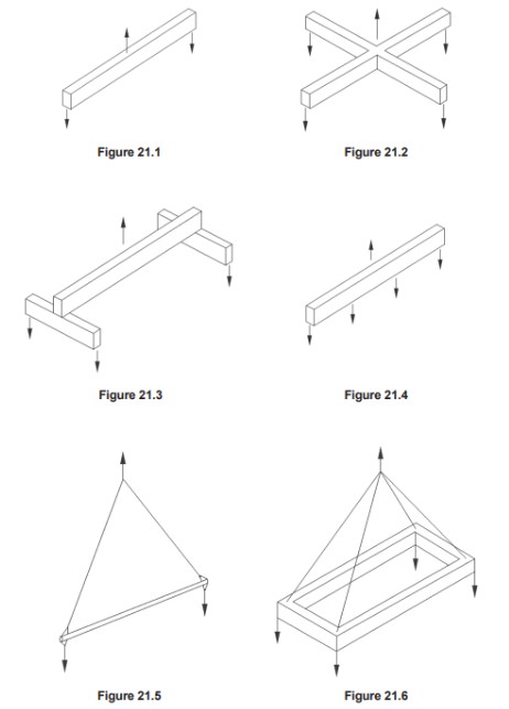
The types of lifting beam are diagrammatically represented in figures 21.1 to 21.4. It will be noted that the suspension points are shown as being vertically below the crane hook. Although single suspension points are shown, multiple suspension points for use with two or more crane hooks can be provided, as can multiple load
attachment points.
21.3.2 Lifting Spreader
A lifting spreader is diagrammatically represented in figure 21.5. It can be considered to be a strut in pure compression. The line of action of the top sling and the load suspension point coincide at the neutral axis at the
end of the spreader
Note
Some bending will be induced due to self weight and the position of the suspension and attachment points and the direction of the load applied to them
Some bending will be induced due to self weight and the position of the suspension and attachment points and the direction of the load applied to them
21.3.3 Lifting Frame
A lifting frame is diagrammatically represented in figure 21.6, which is in effect a combination of four spreaders.
A lifting frame is diagrammatically represented in figure 21.6, which is in effect a combination of four spreaders.
21.3.4 Combination Beams and Spreaders
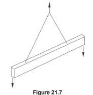
In addition to the above types there can be a combination of a beam and spreader. One of the simpler forms is represented in figure 21.7
In addition to the above types there can be a combination of a beam and spreader. One of the simpler forms is represented in figure 21.7
Note
For the purpose of the code, lifting beams, spreaders, frames and combination beams and spreaders will be referred to under the generic term ‘lifting beam’.
For the purpose of the code, lifting beams, spreaders, frames and combination beams and spreaders will be referred to under the generic term ‘lifting beam’.
21.4 PRINCIPLES FOR THE SELECTION OF LIFTING BEAMS, SPREADERS AND FRAMES
21.4.1 Application of Lifting Beams
Lifting beams are used for various purposes as detailed below.
(1) To reduce the headroom required when lifting long loads.
(2) To provide multiple lifting points.
(3) To provide a means of handling out of balance loads.
(4) To provide a vertical lift with controlled or no inward pull for:
(a) eyebolts and similar lifting points.
(b) loads which must be protected from crushing forces.
(5) To provide a means of handling loads requiring special attachments such as hooks, plate clamps, etc.
(6) To provide a means of using two cranes in tandem.
(7) To provide lifting points at adjustable centres
21.4.2 Stability
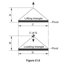
It should be noted that in the majority of cases, the use of a lifting beam instead of long slings will reduce the overall stability of the lift. Particular attention should be paid to the stability of the load when the lifting points are below the centre of gravity. Figure 21.8 shows the limiting condition for instability. To achieve a stable configuration, the height of the lifting triangle must be increased in relation to the loading triangle; i.e. for stability, ‘A’ must be greater than ‘B’ and ‘D’ must be equal to or greater than ‘C’
It should be noted that in the majority of cases, the use of a lifting beam instead of long slings will reduce the overall stability of the lift. Particular attention should be paid to the stability of the load when the lifting points are below the centre of gravity. Figure 21.8 shows the limiting condition for instability. To achieve a stable configuration, the height of the lifting triangle must be increased in relation to the loading triangle; i.e. for stability, ‘A’ must be greater than ‘B’ and ‘D’ must be equal to or greater than ‘C’
21.4.3 Beam Weight
The weight of the lifting beam, together with its associated lifting accessories, must be added to the weight of the load when assessing the total load imposed on the crane hook.
The weight of the lifting beam, together with its associated lifting accessories, must be added to the weight of the load when assessing the total load imposed on the crane hook.
21.4.4 Lifting Accessories
Many lifting beams are fitted with standard lifting accessories such as shackles, wire rope slings, chain slings, web slings, plate clamps, turnbuckles, etc. The requirements of the individual sections of this code apply whether these items are readily removable from the beam or not. Whilst removable lifting accessories can be used for separate lifting applications, it is good practice to keep them together as if forming an integral part of the lifting beam. This is particularly the case if they are recorded with the beam on the documentation required by the supply legislation, manufacturers certificate, report of thorough examination, etc. In the case of lifting accessories used separately, the onus is on the user to replace or reassemble these onto the beam. Care should also be taken to ensure that the component has in fact been thoroughly examined in accordance with current legal requirements and the relevant section of this code before using it for a different lifting application
21.5 INFORMATION WHICH SHOULD BE EXCHANGED BETWEEN THE USER AND THE DESIGNER OR SUPPLIER
The following is the minimum amount of information which should be exchanged between the user and designer
or supplier of a lifting beam
The following is the minimum amount of information which should be exchanged between the user and designer
or supplier of a lifting beam
(1) The reason for using a lifting beam instead of other methods of handling the load.
(2) The total maximum weight of the load to be lifted together with any other forces which may be superimposed on the load.
(3) A detailed description or drawing of the load to be lifted together with principal dimensions which affect the lifting operation including information on the position of the centre of gravity and available headroom.
(4) Details of external obstructions to the use of the beam. Attention is drawn to the fact that a lifting beam could foul the structure of a double beam crane before the upper limit is reached.
(5) The exact type, dimensions and capacity of the crane hook and SWL of the crane. Particular attention should be paid to the safety catch fittings and guards.
(6) The speed and duty rating of the crane.
(7) Frequency of use.
(8) Environmental considerations such as extremes of temperature or corrosive atmospheres.
(9) The level of operatives’ skill and ergonomic considerations. It should be made clear if the beam is to be used by unskilled labour or if the design of the lifting operation requires the attention of a skilled fitter. If manipulation of the beam is necessary in order to carry out the lift, then the labour availability and requirements should be specified.
(10) Operating assembly and storage instructions.
(11) Any additional tests required by the purchaser.
(12) The weight of the lifting beam
21.6 LEGAL REQUIREMENTS
Particular attention is drawn to section 1 subsection 1.3 of this code.
Particular attention is drawn to section 1 subsection 1.3 of this code.
21.6.1
The definition of lifting equipment and accessories used in this code make it clear that the lifting beams, spreaders and frames covered in the scope of this section of the code fall under the definition of lifting accessories. Unless a written scheme of examination, (for guidance refer to LEEA 032 Guidance to written schemes of examination) drawn up by a Competent Person, is in place and operating they must be thoroughly examined by a Competent Person at intervals not exceeding 6 months. Reports of thorough examination should be retained and cross referenced to the equipment’s historical records for inspection by the Competent Person or local enforcing authority.
21.6.2
Following a repair, lifting beams must be re-verified by a Competent Person. In the case of structural repairs, the verification will usually be by way of a proof test and thorough examination. The report of the verification should
be retained and cross referenced to the equipment’s historical records for inspection by the Competent Person or local enforcing authority.
Note
LEEA 055 Verification of lifting beams, spreader and frames, contains detailed information, including verification, following repair for this equipment
LEEA 055 Verification of lifting beams, spreader and frames, contains detailed information, including verification, following repair for this equipment
21.6.3
In the case of the replacement of lifting accessories with components which are identical in every respect, the initial documentation for the replacements should be retained and cross referenced to the equipment’s historical records for inspection by the Competent Person or local enforcing authority.
In the case of the replacement of lifting accessories with components which are identical in every respect, the initial documentation for the replacements should be retained and cross referenced to the equipment’s historical records for inspection by the Competent Person or local enforcing authority.
Note:
It is not uncommon for users to manufacture, or have manufactured to their specifications and drawings, lifting beams, spreaders and frames which they then send to a lifting equipment company for test and examination. Under older legislation, the company making the verification would have issued a test certificate, which allowed the item to enter service. Under current legislation this is no longer the case and it is the user who is the responsible person (legal) with the duty to comply with and issue marking and documentation in accordance with the applicable supply legislation to allow the item to enter service. The testing organisation will only issue a report of a test to the responsible person (legal) for retention in their technical file.
It is not uncommon for users to manufacture, or have manufactured to their specifications and drawings, lifting beams, spreaders and frames which they then send to a lifting equipment company for test and examination. Under older legislation, the company making the verification would have issued a test certificate, which allowed the item to enter service. Under current legislation this is no longer the case and it is the user who is the responsible person (legal) with the duty to comply with and issue marking and documentation in accordance with the applicable supply legislation to allow the item to enter service. The testing organisation will only issue a report of a test to the responsible person (legal) for retention in their technical file.
21.7 MARKING, STORAGE AND HANDLING
21.7.1 Marking
In addition to the marking required by the applicable legislation and the standard being worked to, the following shall be permanently and legibly marked on each lifting beam:
(1) Identification mark. This should be repeated on all detachable components. (If the manufacturer has not provided a unique serial number then it is the responsibility of the user to add the identification mark to identify the equipment with the inspection and examination reports)
(2) Working load limit and SWL, if different.
(3) The name and address of the manufacturer
(4) Year of construction
(5) Total mass of the assembly
(2) Working load limit and SWL, if different.
(3) The name and address of the manufacturer
(4) Year of construction
(5) Total mass of the assembly
Note 1:
Some lifting beams have multiple lifting points and the maximum working load may depend upon the lifting points in use. The marking must clearly show the permitted options and the maximum working load for each.
Some lifting beams have multiple lifting points and the maximum working load may depend upon the lifting points in use. The marking must clearly show the permitted options and the maximum working load for each.
Note 2:
Some lifting beams are of modular design and the maximum working load may depend upon the configuration. If it is impractical to show the maximum working load for all configurations, a code may be used to identify the capacity of each component part and that code used in the manufacturer’s instructions to determine the maximum working load for the particular configuration.
Note 3:
Where the orientation of the beam is not obvious, this should also be indicated. A ‘this way up’ arrow may suffice.
Where the orientation of the beam is not obvious, this should also be indicated. A ‘this way up’ arrow may suffice.
Note 4:
Occasionally lifting beams are fitted with fork lift pockets. These pockets are either intended to allow a fork lift truck to lift the load with the lifting beam or to allow the beam to be moved from location to location only. Whatever the intention, it is important that they are marked appropriately for their intended use, i.e. for lifting the unladen lifting beam only.
Occasionally lifting beams are fitted with fork lift pockets. These pockets are either intended to allow a fork lift truck to lift the load with the lifting beam or to allow the beam to be moved from location to location only. Whatever the intention, it is important that they are marked appropriately for their intended use, i.e. for lifting the unladen lifting beam only.
21.7.2 Storage and Handling
When not in use, lifting beams should be stored in a proper manner to prevent damage. The general requirements are as in section 1 of this code, i.e. the storage area should be dry, free from injurious pollution and extremes of temperature, together with the following:
When not in use, lifting beams should be stored in a proper manner to prevent damage. The general requirements are as in section 1 of this code, i.e. the storage area should be dry, free from injurious pollution and extremes of temperature, together with the following:
(1) Special stands or packing should be provided to support the beam if it will not stand on its own.
(2) Particular attention should be paid to beams that are designed to be dismantled for transportation and storage. Whilst in storage, the component parts should be positively identified and kept together. Only the manufacturer’s component parts or parts manufactured to the same specification should be used in reassembly. There are certain cases where re-verification, e.g. a test and examination, may be required on reassembly and advice must be sought from the manufacturer or other competent authority on this point.
(2) Particular attention should be paid to beams that are designed to be dismantled for transportation and storage. Whilst in storage, the component parts should be positively identified and kept together. Only the manufacturer’s component parts or parts manufactured to the same specification should be used in reassembly. There are certain cases where re-verification, e.g. a test and examination, may be required on reassembly and advice must be sought from the manufacturer or other competent authority on this point.
(3) A lifting beam fitted to a crane hook without the load attached is a load in its own right and all the rules governing operation of a crane or hoist with a load attached must be observed. In certain cases, a lifting beam suspended without the load may be very unwieldy and care must be taken in handling the beam on its own. This applies particularly to low headroom lifting beams
21.8 IN-SERVICE INSPECTION AND MAINTENANCE
21.8.1 Pre-use inspection
In addition to the thorough examination necessary under statutory provisions, all lifting beams should be visually inspected by a suitably qualified and experienced person prior to use or on a regular basis. For lifting beams in regular use it is good practice to make an inspection at the start of each shift or working day. For lifting beams used infrequently it should be done before each use on each day of use.
It is recommended that a formal system of pre-use inspection is implemented, and a written record kept identifying the date inspected, confirmation that it passed inspection and the name and signature of the person making the inspection. In the event that it does not pass inspection, there should be procedure to quarantine the lifting beam to prevent further use of the equipment until the problem has been resolved.
The purpose of the pre-use inspection is to check functionality of the lifting beam and make a visual check for any obvious defects. This inspection must be carried out with the lifting beam in a reasonably clean condition and in adequate lighting. The following are examples of the common defects which may become apparent in use or during the regular inspection of lifting beams and if any are present, the lifting beam should be withdrawn from service and referred to a Competent Person.
(1) Lifting eyes, bows, bolts, etc, should be inspected for obvious signs of wear, distortion and physical damage.
(2) Load attachment points such as hooks fabricated into the beam should be inspected for wear, distortion and physical damage.
(3) Slewing, tilting, sliding, etc. devices should be inspected for any damage affecting functionality and operation.
(4) Attachment points for shackles used for lifting the beam or attaching the load should be inspected for wear and elongation of holes. It is usually necessary to remove the shackle to do this.
(5) Bolted connections to the beam should be checked for tightness.
(6) The beam should be checked for distortion.
(7) The beam should be checked for localised physical damage. Particular attention should be given to hollow sections which may have dents or localised buckling and to the flanges of structural steel sections.
(8) Corrosion damage.
(9) Signs of cracks and distortion especially in welded details.
(10) Ensure that requisite markings are clearly visible and correspond to the loadings stated on the documentation.
(11) Lifting accessories, such as shackles, eyebolts, wire rope slings, chain slings, synthetic web slings, plate clamps, hooks, turnbuckles, etc. should all be inspected in accordance with the respective sections of this code
Note:
If the equipment is damaged, advice should be sought from a Competent Person. Repairs should only be carried out by competent manufacturers or under the supervision of a Competent Person
If the equipment is damaged, advice should be sought from a Competent Person. Repairs should only be carried out by competent manufacturers or under the supervision of a Competent Person
21.8.2 Interim Inspection
In addition to the thorough examination and pre-use inspection some lifting beams will require an interim inspection(s). The number, frequency and extent of the interim inspections is based on a risk assessment taking into account the possibility of deterioration of components or assemblies due to the specific conditions of use, to ensure that defects are identified and remedied before they become a danger to persons.
In addition to the thorough examination and pre-use inspection some lifting beams will require an interim inspection(s). The number, frequency and extent of the interim inspections is based on a risk assessment taking into account the possibility of deterioration of components or assemblies due to the specific conditions of use, to ensure that defects are identified and remedied before they become a danger to persons.
The risk assessment must take account of the manufacturer’s literature and actual conditions of use, for example environmental conditions and utilisation that can cause deterioration. The inspection can be restricted to those critical components identified in the risk assessment and therefore they do not have to be as detailed and time consuming as a thorough examination. Typically the inspection will be a more detailed inspection of one or more of the items listed in 21.8.1, but may also cover some or all of the components covered by the thorough examination (refer to the manufacturers literature or LEEA Lifting equipment examiners hand book for guidance to defined scopes of thorough examination including acceptance and rejection criteria).
Interim inspections are often done at the same time as planned maintenance, see 21.8.3 below
21.8.3 Maintenance
Routine preventive maintenance should be carried out according to the manufacturer’s instructions in addition to any requirements of the particular site due to the conditions of service. Lifting accessories, such as shackles, eyebolts, wire rope slings, chain slings, synthetic web slings, plate clamps, hooks, turnbuckles, etc. should all be inspected in accordance with the respective sections of this code.
Routine preventive maintenance should be carried out according to the manufacturer’s instructions in addition to any requirements of the particular site due to the conditions of service. Lifting accessories, such as shackles, eyebolts, wire rope slings, chain slings, synthetic web slings, plate clamps, hooks, turnbuckles, etc. should all be inspected in accordance with the respective sections of this code.
Adequate lubrication shall be applied to the moving parts of lifting beams where applicable and in accordance with the manufacturer’s instructions. For certain applications, i.e. where there is a risk of contaminating other goods or products for example or where dirt is liable to mix with the lubricant for example, it may be desirable to use a dry lubricant spray. Any travel limits should be checked to ensure that they are correctly set and that the limit mechanism and switches operate freely and correctly.
In the case of any lifting beam which incorporates contactors, whether internal to the lifting beam or as a part of the control gear, they should be checked for wear and signs of arcing. They should be cleaned, maintained or replaced in accordance with the manufacturer’s instructions.
21.8.4 Thorough examination
The lifting beam must regularly be thoroughly examined by a Competent Person to check whether it remains safe to use. This is to be done within a maximum period of 6 months unless a written scheme of examination (for guidance refer to LEEA 032 Guidance to Written Schemes of Examination), drawn up by a competent person is in place and operating.
The lifting beam must regularly be thoroughly examined by a Competent Person to check whether it remains safe to use. This is to be done within a maximum period of 6 months unless a written scheme of examination (for guidance refer to LEEA 032 Guidance to Written Schemes of Examination), drawn up by a competent person is in place and operating.
Reports of thorough examination should be compliant with the legal requirements or the LEEA template report documents, retained and cross referenced to the lifting beam’s historical records for inspection by the Competent Person or the enforcement authority.
Any defects found by the examination should be reported to the owner of the equipment, who must assess the root cause of the defect and implement procedures to prevent reoccurrence, e.g. training of operators, increased inspections, etc., before remedying the equipment and returning it to service. The competent person may deem it necessary to supplement their examination with testing. Such testing could be NDT, overload testing, etc. The nature and extent of testing is always at the discretion of the competent person in support of their thorough examination.
Note:
Unless a mandatory requirement of the applicable national legislation or manufacturer, LEEA does not recommend the routine overload testing of lifting beams, except following an exceptional circumstance such as significant modification or repair. This is because overload testing has few benefits and number of disadvantages;
Unless a mandatory requirement of the applicable national legislation or manufacturer, LEEA does not recommend the routine overload testing of lifting beams, except following an exceptional circumstance such as significant modification or repair. This is because overload testing has few benefits and number of disadvantages;
- Some manufacturers do not recommend overload tests, except in ‘exceptional’ circumstances.
- Repeated overloads can cause deterioration of the equipment over time.
- Most failures are the result of defects such as deformation, fatigue cracking, etc. that will not be revealed by an overload test but can be identified during thorough examination.
- Defects such as deformation, fatigue cracking, etc. can be made worse by overload testing but may still not be identified by the test.
- Inspection bodies do not recommend it as there is no defined structural or mechanical benefit
In addition to any specific instructions relating to the safe use of the lifting beam issued by the manufacturer, the following points should be observed. Reference should also be made to the individual sections of this code for the safe use of loose and detachable lifting accessories.
(1) Most lifting beams and spreaders are designed for a specific purpose and should not be used for other purposes without reference to a Competent Person.
(2) Lifting beams with lifting points designed for a particular crane hook size should always be used on the specified hook. Failure to do so can cause damage to both the hook and the lifting point.
(3) When using a lifting beam designed for operating with two cranes in tandem, the rules for multilifting and reducing the lifting capacities of the cranes must be observed. Refer to the equipment manufacturers instructions or suitable LEEA member organisation for guidance
(4) The use of load manipulation devices such as tag lines, Push/Pull Poles , etc is essential when manipulating long loads on a beam with a single suspension point. Where tag lines are used they should be of adequate length so that the personnel controlling the load can stand well clear of it. Tag lines must not be used to attempt to balance the load.
(5) The lifting beam should remain in its intended attitude during use.
(6) Lifting beams with multiple attachment points need particular attention to ensure that the SWL on the individual point is not exceeded.
(7) When lifting or setting the load down, care should be taken to ensure that individual load attachment points are not overloaded.
(8) The lifting beam should not be allowed to foul the underside of the crane structure. If this is possible then consideration should be given to adjusting the limit switch of the crane to a lower position.
(9) The weight of the beam must be added to the weight of the load when assessing the overall load on the crane hook.
(10) When using beams with adjustable lifting points, particular care must be taken to ensure that the manufacturer’s specified loadings for the centres chosen are not exceeded
21.10 TRAINING
In addition to the training requirements specified in section 1 subsection 1.9 of the code, operative training should take the manufacturer’s instructions into account, paying particular attention to the following:
(1) Operatives and drivers should be informed of the specific uses for which the lifting beam is intended. They should be shown the correct method of attaching the lifting beam or to the crane hook and the correct method of attaching the load to the lifting beams..
(2) In the case of beams which are dismantled for transportation and storage, operatives should be shown the correct method of assembling the lifting beam